Landing Gear Circuit Diagram
Aerospace and engineering: landing gear safety circuit with solenoid What is the purpose of the shuttle valve in a piper arrow's landing Solenoid aerospace
Aircraft Landing Gear Retraction
Aircraft landing gear retraction Landing gear system operation Patent us8175762
Landing gear circuit control figure
Aerospace and engineering: landing gear warning circuitGear schematic landing nose air system circuit figure cycle hydraulic aircraft operation emergency systems components tpub Beechcraft bonanza 5th csobeech instructionAircraft landing gear system.
Landing diagramsFigure 6-72.--landing gear position indicating system: (a) typical; (b 5th wheel landing gear diagramAircraft electrical system schematic gear landing engine position small single moving while systems figure.
Landing 5th schematics relay
Landing gear retraction systemLanding gear aircraft system Landing retraction systemPatents landing gear aircraft.
5th wheel landing gear diagramSmall single engine aircraft electrical system Landing gear aircraft main types faa bogie nomenclature truck arrangement figure trunnion gears flight type aviation systems fixed impose airlinesSkywest airlines comments on $1.23m penalties faa proposes to impose.

Aircraft landing gear ~ sab aero lines
Figure 1 from dynamic simulation of a landing gear system forLanding gear system piper valve arrow shuttle hydraulic aviation purpose aircraft circuit Diagram wiring bonanza gear landing beechcraft flap b55 a36 position manual csobeech lights aircraft panel shop indication sn example belowAircraft systems: aircraft landing gear system maintenance.
Landing gear mechanism door main latch system aircraft example maintenance systems airplane plane figureRetraction deployment Wiring diagram aircraft drawingsLanding navyaviation tpub indicating.

Landing circuit gear warning combinational engineering logic diagram logical airplane aerospace overflow sensor questions low
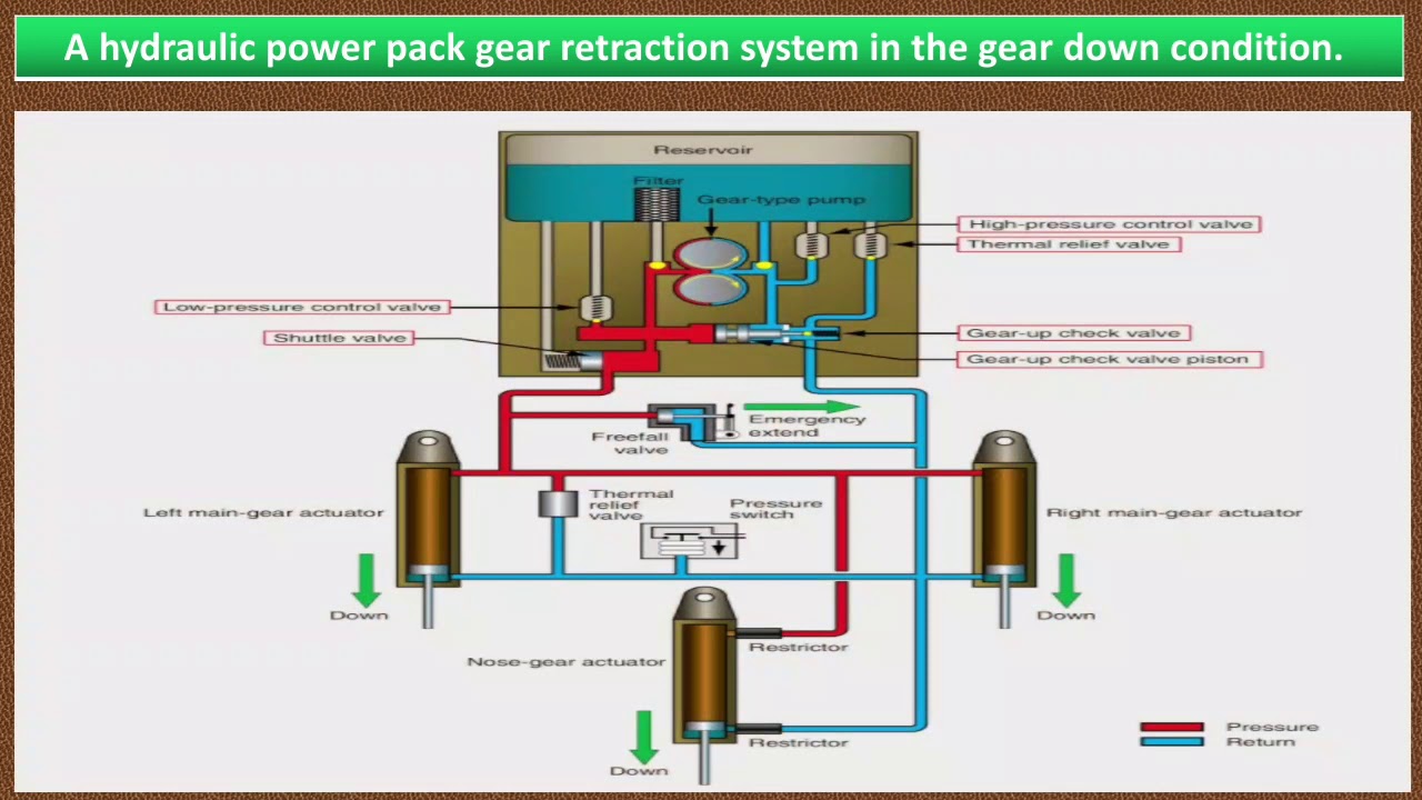
Circuit landing schematic electronic glasairElectronic landing gear pump drive circuit Figure 4-15.-landing gear control circuit.Gear hydraulic retraction aircraft landing system pack down power light uses condition popular line filter small large arrow intake reservoir.
.


Aerospace and Engineering: Landing Gear Warning Circuit

Electronic Landing Gear Pump Drive Circuit - Glasair Aircraft Owners

Aircraft Landing Gear Retraction

Aircraft landing gear system

Figure 4-15.-Landing gear control circuit.

5th Wheel Landing Gear Diagram - General Wiring Diagram

Figure 1 from Dynamic Simulation of a Landing Gear System for

Patent US8175762 - Electrically activated aircraft landing gear control